Home > POF Series Programmable Filter Selection Guide

POF Series Programmable Filter Selection Guide

POF Series Programmable Filter Selection Guide

POF Series Programmable Filter Selection Guide

The POF family is built around an LCOS-based programmable optical filter that selects your target wavelength from a dense spectrum and rejects everything else, so a single benchtop instrument can replace a drawer of fixed filters. The same programmable optical filter collection also lists the L variant for liquid crystal spatial light modulator pairing, which is where most model decisions get made. This guide walks through the published parameters, the standard-versus-L choice, and the integration checks worth completing before you ask a programmable optical filter manufacturer for a quote — and it sets out what a cal filter manufacturer should be able to document alongside the unit.

1523.529–1572.681 nmPublished tuning range
±2.5 GHzBandwidth setting accuracy
FC/APC + USBOptical and control interfaces
Programmable Optical Filter POF-1100
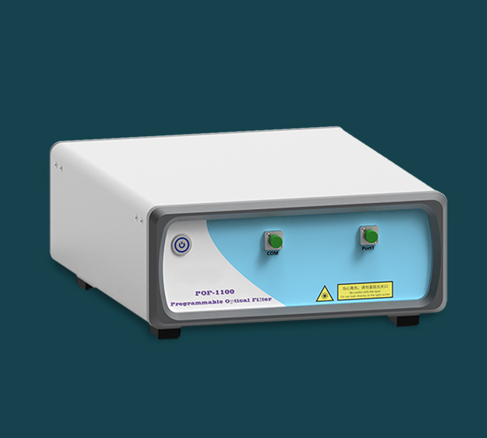
Programmable Optical Filter POF-1100 LCOS benchtop instrument, compact housing view

Inside the POF-1100: LCOS Filtering in a Benchtop Housing

The POF-1100 is an instrument designed for wavelength selection. It can pick the desired wavelength from numerous options while the others are rejected. Because the filtering is built on liquid crystals on silicon (LCOS), the instrument enables extremely fine modulation of light beams, and the product can switch optical wavelength channels dynamically from any input to any output.

  • Programmable by designFine control over wavelength, bandwidth and phase, with configuration handled from software rather than by swapping hardware.
  • Built for the benchCompact benchtop housing with a modular architecture that is compatible with standard optical benches.
  • Aimed at laboratory workEngineered primarily for research laboratories and optical test bench applications that need accurate wavelength management, including spectral experiments and system calibration.
  • Repeatable run to runA single programming interface supports stable repeatability of wavelength and bandwidth configurations.

Published POF-1100 Parameters

These are the values stated for the POF-1100 configuration. Use them as the baseline for every comparison on this page, and confirm any parameter that is not listed here against the specific model you intend to order.

ParameterPublished valueNotes
TechnologyLiquid crystals on silicon (LCOS)High-resolution programmable filter platform
Wavelength range1523.529 nm to 1572.681 nmRange quoted on the product page
Band coverage (as stated)C band and L bandConfirm your exact band requirement before ordering
Bandwidth setting accuracyWithin ±2.5 GHzPrecision of the passband setting
Optical insertion lossBelow 5.5 dBAdd to your link budget
Extinction ratioExceeding 30 dBRejection of out-of-band wavelengths
Optical routing1x1Dynamic channel switching from any input to any output
Optical power handlingUp to 27 dBmInput power limit
Setting timeUnder 500 msReconfiguration speed
Power consumptionBelow 50 WModerate draw for a benchtop instrument
Optical interfaceFC/APCIndustry-standard angled contact connector
Control interfaceUSB (digital control)For integration into photonics test systems
Polarization and flatnessLow polarization-dependent loss, minimal insertion loss rippleSupports high signal integrity

Start With Your Scenario, Not the Spec Sheet

Most model decisions come down to one task and one parameter. Find your task below, read the spec that actually drives the choice, then run the buyer check before you commit.

Telecom calibration

Calibrating transceivers and channel-routing hardware

Deciding spec: the ±2.5 GHz bandwidth setting accuracy and the extinction ratio exceeding 30 dB. Together they set how cleanly you can isolate a channel and how low the leakage floor stays during the measurement.

Buyer check: confirm the band you validate against, and whether you need dynamic channel switching from any input to any output inside a single unit or across several.

Automated test bench

Scripted wavelength sweeps in a rig

Deciding spec: the USB digital control interface and a setting time under 500 ms. Those two numbers decide how many points a scripted sweep can capture in an hour.

Buyer check: verify that your automation stack can drive a USB instrument, and that the FC/APC interface matches every other connector in the optical path.

Spatial light modulation

Experiments that place an SLM in the same optical path

Deciding spec: architecture rather than a figure. The POF-1100L is listed as the version for liquid crystal spatial light modulator pairing, while the standard POF-1100 is sold as the standalone LCOS filter.

Buyer check: read the POF-1100L product page for its own published parameters before you specify the L variant, and confirm the SLM hardware you plan to pair it with.

Power and loss budget

High-power inputs or loss-sensitive links

Deciding spec: optical power handling up to 27 dBm and insertion loss below 5.5 dB. The first caps what you can feed in; the second is the penalty you carry in every measurement.

Buyer check: add the insertion loss to the loss of your DUT and patch cords, then confirm the detector still sees enough power at the far end.

Band coverage

Confirming C band, L band or a mixed requirement

Deciding spec: the product page states C band and L band coverage alongside a quoted tuning range of 1523.529 nm to 1572.681 nm. The band you actually work in decides whether one unit is enough.

Buyer check: state your exact band requirement in the quote request so the configuration can be confirmed in writing before purchase.

Photonics prototyping

Real-time spectral shaping during system validation

Deciding spec: programmable wavelength, bandwidth and phase control, used as a core element inside a test rig for system-level validation.

Buyer check: plan the control software early, and decide whether the filter will be reconfigured by an operator or called from an automated sequence.

Standard POF-1100 or the L Variant?

Both are LCOS-based programmable optical filters. The difference is the architecture the filter is built to sit inside.

POF-1100 — standalone LCOS filtering

  • LCOS-based programmable optical filter for wavelength, bandwidth and phase control.
  • FC/APC optical interface with USB digital control.
  • 1x1 optical routing with dynamic channel switching from any input to any output.
  • Compact benchtop housing; power consumption below 50 W.
Choose this if your work is wavelength selection itself: equipment calibration, channel validation, spectral shaping or component characterisation on a bench.

POF-1100L — LCOS filtering for SLM pairing

  • Listed on this site as the programmable optical filter for liquid crystal spatial light modulator pairing.
  • Built on the same LCOS filtering approach as the standard unit.
  • Intended for laboratories that place wavelength selection alongside spatial light modulation hardware.
  • Its own published parameters sit on the POF-1100L product page — confirm them before specifying.
Choose this if the experiment needs spatial light modulation and programmable filtering in the same optical path, rather than filtering alone.

What Each POF-1100 Spec Means in a Measurement

Six numbers carry almost all of the practical weight. Here is what each one changes about the data you collect.

±2.5 GHz

Bandwidth setting accuracy

How precisely the passband edges can be placed. It decides whether you can isolate tightly spaced channels or trace a component's roll-off, rather than simply blocking broad wavelength regions.

< 5.5 dB

Insertion loss

Every measurement carries this penalty. Add it to the loss of the device under test and the patch cords before you conclude the link still delivers enough power to the detector.

> 30 dB

Extinction ratio

How completely rejected wavelengths stay rejected. On high-dynamic-range measurements, leakage through the filter becomes the noise floor, so this figure sets the limit on what you can resolve.

< 500 ms

Setting time

How fast the filter moves to a new configuration. In a scripted bench this is a direct multiplier on throughput: shorter settings mean more wavelength points per hour.

Low

Polarization-dependent loss

If the polarization state at the filter input is not controlled, low PDL keeps measured power steady as that state drifts — one less source of variation to explain in the results.

Minimal

Insertion loss ripple

A flat passband means the power you measure inside the band reflects the device under test rather than the shape of the filter itself.

Programmable Optical Filter POF-1100 with FC/APC and USB interfaces for bench integration

Will It Fit Your Rig and Your Software?

Four integration questions decide whether the filter drops into an existing bench or forces a rework of the rack.

FC/APC optical interfaceMatches the angled-contact connectors used across optical benches. Check your patch cords and any adapter panels along the path.
USB digital controlOne digital control interface for integration into photonics test systems. Plan for a USB host in the rack and confirm your automation software can address it.
Compact benchtop footprintMechanical dimensions are intended for compatibility with standard optical benches, so the unit can sit inside an existing test rig.
Power below 50 WModerate consumption for a benchtop instrument — no dedicated circuit required in a typical laboratory.
Modular architectureDesigned for modular integration, which matters if the bench will be reconfigured as experiments change.
1x1 optical routingDynamic channel switching from any input to any output, driven entirely from software.

Request a Quote or Plan a Multi-Unit Purchase

Send your band, the bandwidth accuracy you need and how the filter will be controlled, and the configuration can be confirmed against your test bench before anything ships.

1. Send your requirement Band coverage, required bandwidth setting accuracy, power level at the input, and the connectors already in your rig.
2. Confirm the configuration The team matches the model and interface details — FC/APC and USB control — to the way your bench is set up.
3. Order and integrate Raise quantities for project or multi-unit builds, and ask integration questions in the same request.

Related Reading

Three notes to help clarify product requirements before contacting the supplier.

The Value of a Programmable Optical Filter in Telecommunications Calibration

Programmable optical filters enable rapid, precise wavelength selection with bandwidth accuracy within a few GHz, enhancing calibration efficiency and signal integrity in telecom t

Read article

Key Features of a Tunable Optical Filter for Optical Test Benches

Programmable optical filters offer adjustable bandwidth from 8 GHz to 6 THz, low insertion loss below 5.5 dB, and compact USB-controlled designs for versatile, precise optical test

Read article

Comparing Programmable Optical Filter Solutions for Photonics Research Labs

The POF-1100 programmable optical filter offers precise wavelength control across 1523.529–1572.681 nm with sub-500 ms reconfiguration, supporting efficient spectral shaping in pho

Read article

Frequently Asked Questions

what is a programmable optical filter used for?

it is an instrument designed for wavelength selection: it can select the desired wavelength from numerous options while the others are rejected. in practice it is used in research laboratories and optical test bench applications for wavelength-selective experiments, system calibration, spectral shaping, and validation of wavelength-selective components and channel routing architectures.

what wavelength range and bands does the pof-1100 cover?

the published tuning range is 1523.529 nm to 1572.681 nm, and the product copy states c band and l band coverage. because the band you actually work in decides whether one unit is enough, state your exact band requirement when you request a quote so the configuration can be confirmed.

how accurate is the bandwidth setting?

the published bandwidth setting accuracy is within ±2.5 ghz. that figure determines how precisely passband edges can be placed, which matters when you need to separate closely spaced channels or trace a component's roll-off.

how does the pof-1100 connect to a test setup?

the optical interface is fc/apc and control is handled over a usb digital interface, which supports integration into photonics test systems and automated control. the unit is a compact benchtop instrument with power consumption below 50 w and optical power handling up to 27 dbm.

what is the difference between the pof-1100 and the pof-1100l?

both use lcos filtering technology. the pof-1100 is the standalone programmable optical filter, while the pof-1100l is listed as the version for liquid crystal spatial light modulator pairing. read the pof-1100l product page for its own published parameters before you specify the l variant.

can i request a quote or plan a multi-unit purchase?

yes. send your band, bandwidth accuracy requirement, input power level and control preferences through the contact page. the team can confirm the model and interface details against your bench, and multi-unit or project quantities can be discussed in the same request.